The Ten-Twenty Electrode System of the International Federation
George H. Klem* (USA), Hans Otto Lüders (US), H.H. Jasper (Canada and C. Elger (Geermany)
The position of electrodes placed should be based on specific measurements of standard skull landmarks. The measurements should be proportional to the size and shape of the skull.
Adequate coverage of all parts of the head should be provided with standard electrode placement.
Electrode designations would be expressed in terms of brain areas covered rather than only in numbers. This would make communications more meaningful to the non-spacialist, as well as workers in other laboratories.
Technique of Measurement
The measurement technique is based on standard landmarks of the skull. Namely, the nasion, inion, and the left and right preauricular points. The preauricular points are felt as depressions at the root of the zygoma, just anterior to the tragus.
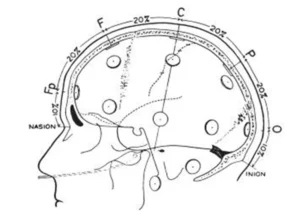
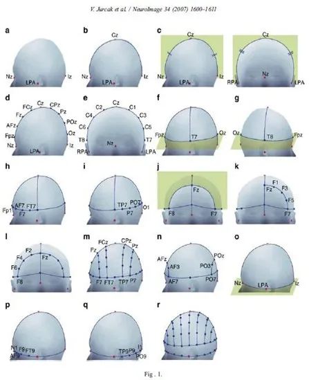
The first measurement is in the anterior-posterior plane through the vertex, taken from the nasion to the inion. This measurement is divided into 5 separate areas (see fig.1).
The first mark is placed at 10% of the total measurement and labeled Fp. The second, third, fourth and fifth marks are placed at 20% intervals of the total measurement and labeled F, C, P, and O. Note that the O mark would be located at 10% of the measurement above the inion. The expression Fp, F, C, P and O represent the fronto polar, frontal, central, parietal and occipital areas, respectively.
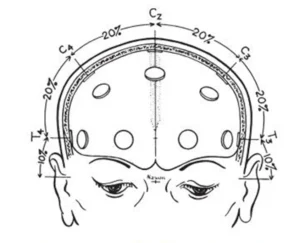
Lateral measurement of the central coronal plane strats at the left preauricular point thrugh the C vertex mark to the right preauricular point (fig.2). A mark is placed at 10% of this measurement over the preauricular points and labeled T.
The expression T represents the temporal area. Marks are then located at 20% of the lateral measurement and labeled left and right C, and the C vertex location is crossed.
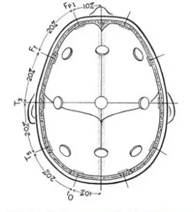
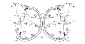
A circumferential measurement (fig.3) is then taken over the temporal lobes from the midline Fp position to the midline O position.
A mark is made at 10% of this measurement indicating the left or right Fp electrode position. Marks are then made at 20% of the measurement and are labeled inferior frontal, mid-temporal, and posterior temporal and left or right occipital (note that the mid-temporal electrode positions are crossed). The remaining 10% measurement from the left and right occipital marks would be the midline = position. Variations of this measurement have been described by Harner and Sannit (1974)
Fig.1 Lateral view oof skull to show methods of measurement from nasion to inion at the midline. Fp is frontal pole position, F is the frontal line of electrodes, C is the central line of electrodes, P is the parietal line of electrodes and O is the occipital line. Percentages indicated represent proportions of the measured distance from the nasion to the inion. Note that the central line is 50% of this distance. The frontal pole and occipital electrodes are 10% from the nasion and inion, respectively. Twice this distance, or 20% separates the other lines of electrodes
Fig.2 Frontal view of the skull showing the method of measurement for the central line of electrodes as described in the text.
Fig.3 Superior view with cross section of skull through the temporal line of electrodes illustrating the 10-20 system applied in this direction as described in the text
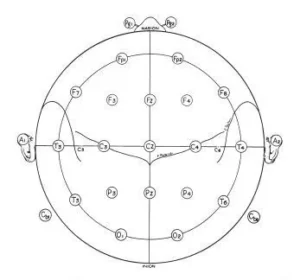
Antero-posterior measurements are taken from the left and right Fp position through the lateral C position to the left and right O position. This measurement is then divided equally by 25% marks and labeled lateral F, lateral C, and lateral P. Anterior coronal measurements are taken from the left and right inferior frontal position through the midline F position and divided into 25% segments, making crosses at the left lateral frontal, F vertex and right lateral frontal positions. A posterior coronal measurement is taken from the left posterior temporal mark through the midline P position and this is also divided into 25% segments and marks are labeled left lateral P, midline P and right lateral P (fig.4)
These measurements provided for the location of 19 of the 21 electrodes used in the 10-20 electrode system (fig.5). The remaining two electrodes were placed on the ear loves and labeled auricular electrodes. The electrode positions were named in anatomical terms for the cortical areas rocerded, with the exception of the “C” electrodes which were termed central since they were located over the central sulcus.
A numbering system was added to differentiate between left and right homologous regions, odd numbers for the left hemisphere, Fp1, F3, F7, C3, T3, P3, T5, and O1. Even numbers for the right hemisphere, Fp2, F4, F8, C4, T4, P4, T6, and O2. The original recommendation called the F, C and P vertex electrodes F0, C0, and P0, but later changed to Fz, Cz, and Pz (z for the zero).
The numbers selected allowed for the additional electrodes to be placed in the coronal plane and have suitable designations (e.g. F2 placed between Fz and F4, and F6 placed between F4 and F8). Other additional electrodes included pharyngeal and cerebellar elelectrodes which were termed Pg, Pg2, Cb1, and Cb2, resspectively.
Anatomical Studies
Anatomical studies were performed on the heads of cadavers to determine the cortical areas covered by each electrode position. Measurements were taken and the 10-20 system marked on the skulls, and electrodes were applied. Drill holes were placed through the skull and the underlying cortex was marked with India ink before removing the brain for examination. It was concluded that while there was some variability, the two principle fissures, central and sylvian, were within ±1cm of the marks shown on Fig.6.
Fig.4 the lateral view of left and right hemipshere showing all standard electrode psositions, omitting intermediate positions (such as C5 and C6) which are used only for special studies with more closely spaced electrodes. These drawings were made from a series of X-Ray projections with true lateral views. The location of principal fissurees was determined by silver clips placed at operation and bu other anatomical studies described in the text. The location pf pharyngeal electrodes (pg and Pg2) wal also obtained from X-Ray studies with these electrodes in place.
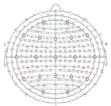
Fig. 6 A single plane projection of the head, showing all standard positions and the location of the rolandic and sylvian fissures. The outer circle was drawn at the level of the nasion and inion. The inner circle represents the temporal line of electrodes. This diagram provides a useful stamp for the indication of electrode placements in routine recording.
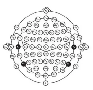
Fig. 7 Modified combinatorial nomenclature
Autori
Prof. Paolo Onorati Dip. Fisiologia e Farmacologia V. Erspamer Università degli Studi di Roma “La Sapienza”
Vuoi prenotare una Prima Visita? Compila subito il Form e inserisci la tua Richiesta, mi metterò in contatto con te il prima possibile.
Tutto Quello che Devi Sapere
Le Domande Frequenti
Scopri le Risposte alle Domande che ricevo più spesso!
Che Tipo di Visite Neurologiche Offro?
Mi occupo di Neurologia in tutte le fasce d’età: bambini, adulti e anziani. Valuto condizioni come Epilessia, Disturbi Cognitivi, Parkinson, Emicrania, ADHD, Disturbi del Sonno, del Comportamento e molto altro.
Dove Posso Ricevere i Miei Pazienti?
Visito principalmente a Roma, in zona Piazza Vescovio, Su richiesta ricevo anche a Roma Sud. Per i pazienti del centro-sud, è possibile prenotare presso il centro Aditerm a Ferentino (FR), con segreteria dedicata.
Eseguo Personalmente gli esami EEG?
Assolutamente Sì. Eseguo e referto personalmente gli EEG, anche in sonno spontaneo o dopo deprivazione, quando indicato. È uno strumento fondamentale per la diagnosi in neurologia, e preferisco occuparmene in prima persona.
Dopo la Visita, Posso Essere Ricontattato?
Sì. Offro un contatto diretto Post-Visita per chiarimenti, aggiornamenti terapeutici e/o Follow-Up. Preferisco ricevere messaggi scritti via Whatsapp, così posso rispondere con cura, anche se non in tempo reale.
Mi Occupo Anche di Neurologia Pediatrica?
Assolutamente Sì. Ho una lunga esperienza nella valutazione neurologica di bambini e adolescenti, in particolare nei casi di Epilessia, Disturbi del Neurosviluppo, ADHD, Autismo, Sindrome di Down e Disturbi dell’Apprendimento. Ho svolto per più di 20 anni attività di ricerca e clinica presso il Centro per lo Studio delle Disabilità Infantili, IRCCS San Raffaele Pisana Roma e San Raffaele Cassino, Tosinvest Sanità, Institute for Basic Research in Development Disabilities (IBR, NY), Center of Cerebral Palsy Spasticity presso il St. Louis Children’s Hospital (ST. Louis, Missouri), USA al fianco del Collega ed Amico Prof. Giorgio Albertini. Collaboro stabilmente con il Prof. Giacomo Stella – Università degli Studi di Modena-Reggio Emilia, (SOS Dislessia).
Serve una Prescrizione del Medico di Base per Prenotare?
No. Trattandosi di una consulenza privata, è possibile prenotare direttamente, anche senza impegnativa o richiesta del medico curante.
Quanto Dura una Visita?
Dedico sempre il tempo necessario a ogni Paziente. In media una prima visita dura tra i 45 ed i 90 minuti, ma non guardo l’orologio: l’ascolto e l’attenzione vengono prima di tutto.
Per fornire le migliori esperienze, utilizziamo tecnologie come i cookie per memorizzare e/o accedere alle informazioni del dispositivo. Il consenso a queste tecnologie ci permetterà di elaborare dati come il comportamento di navigazione o ID unici su questo sito. Non acconsentire o ritirare il consenso può influire negativamente su alcune caratteristiche e funzioni.
Funzionale
Sempre attivo
L'archiviazione tecnica o l'accesso sono strettamente necessari al fine legittimo di consentire l'uso di un servizio specifico esplicitamente richiesto dall'abbonato o dall'utente, o al solo scopo di effettuare la trasmissione di una comunicazione su una rete di comunicazione elettronica.
Preferenze
L'archiviazione tecnica o l'accesso sono necessari per lo scopo legittimo di memorizzare le preferenze che non sono richieste dall'abbonato o dall'utente.
Statistiche
L'archiviazione tecnica o l'accesso che viene utilizzato esclusivamente per scopi statistici.L'archiviazione tecnica o l'accesso che viene utilizzato esclusivamente per scopi statistici anonimi. Senza un mandato di comparizione, una conformità volontaria da parte del vostro Fornitore di Servizi Internet, o ulteriori registrazioni da parte di terzi, le informazioni memorizzate o recuperate per questo scopo da sole non possono di solito essere utilizzate per l'identificazione.
Marketing
L'archiviazione tecnica o l'accesso sono necessari per creare profili di utenti per inviare pubblicità, o per tracciare l'utente su un sito web o su diversi siti web per scopi di marketing simili.